Anchor Rod Member
- General Overview
- Step-By-Step
- Tips and Tricks
- Related Tools
General Information
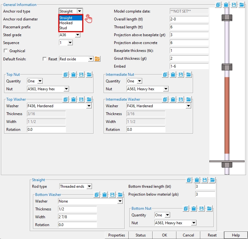
Anchor rod type: Straight or Hook or Stud.
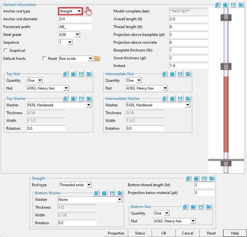
' Straight '
|
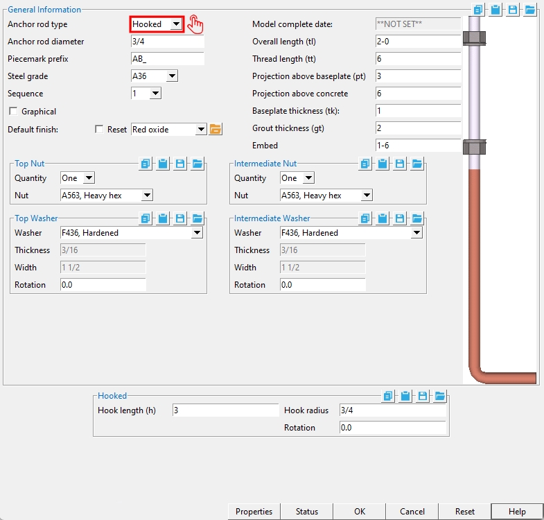
' Hook '
|
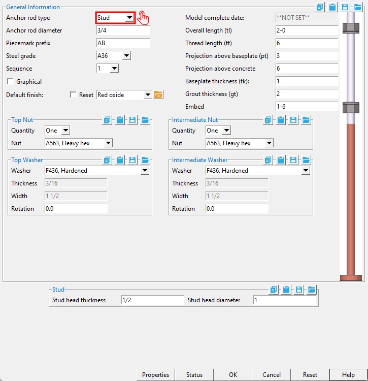
' Stud '
|
'Straight' anchor rods can have 'Threaded ends' or 'Full threads' along their entire length. Being the only type of anchor rod that can have a "Bottom thread length", they are also the only type that can have a "Bottom Washer" and "Bottom Nut".
'Hook' anchor rods are bent 90 degrees into a hooked shape. You can set the "Hook radius" of the 90 degree bend as well as the "Hook length".
'Stud' anchor rods have a stud head at the bottom of their shaft. You can set its "Stud head thickness" and "Stud head diameter". The "Overall length" of a stud anchor rod is equal to its "Projection above concrete" and "Embed" length.
Anchor rod diameter: The diameter of the anchor rod.

Piecemark prefix: Any characters that you want to begin the member piecemark that will be assigned to the anchor rod that you are adding. The piecemark will be assigned when the anchor bar materials are generated (or regenerated), after you press the "OK" button.
This applies to Add Anchor Rod operations. For example, if you were to type in AR_ here, and this is the 89th member you have added, Add Anchor Rod may add 89 after this prefix, thus assigning your new anchor rod member the piecemark AR_89.
If you edit an anchor rod and change its piecemark prefix, the old piecemark will continue to be used.
The prefix entered here will only be used if the anchor rod you are adding does not match another that is already in your model.
Steel grade: A36 or A572 or etc. This is the grade of steel for the round bar that is the anchor rod.
Setup: This "Steel grade" list box
( is populated from Home > Project Settings > Job > Material Grades > Round and Square Bar Grades.)
Sequence: Any sequence name from the Sequence Names setup list can be selected on the list box ![]() )
)
Tip: If you want to add a new sequence so that it can be selected here, you should first increase the number of "Maximum sequences" that are available.
Graphical: Click here for more information.
Default Finish: Click here for more information.
Model complete date: Read-only. The Model complete status of this member can be set using "Update Attributes". You cannot set the "Model complete date" here, on this window.
**NOT SET** indicates that this window is fully editable.
'month day year' indicates that all fields on this window are in a disabled , read-only state due to the "Model completed" date having been set on this member, using Update Attributes, not necessarily on the reported date.
Also see: "Model complete date"
Overall length ( tl ): The distance from the top of the anchor rod to the bottom of the anchor rod. For a 'Hooked' anchor rod, the distance is measured to the bottom of the anchor rod's hook.
|
|
Note: "Overall length" = "Projection above concrete" ( pc ) + "Embed" (em).
Thread length (tt): The distance from the top of the anchor rod (where the threading begins) to where the threading ends.
|
|
Projection above base plate (pt): The distance from the top of the base plate to the top of the anchor rod. The top of base plate is referenced from the bottom of Top Washer or from the bottom of Top Nut if the Top Washer is set to 'None'.
|
|
|
Note: "Projection above base plate" (pt) + "Baseplate thickness" (tk) + "Grout thickness" (gt) = "Projection above concrete" (pc).
Projection above concrete (pc): The distance from the top of concrete to the top of the anchor rod. The top of concrete is referenced from the bottom of grout.
|
|
|
|
Note: "Projection above concrete" (pc) = "Projection above base plate" (pt) + "Baseplate thickness" (tk) + "Grout thickness" (gt).
Baseplate thickness (tk): The thickness of the base plate. This sets the position of the top nut to the top surface of the base plate.
|
|
|
|
Note 1: The "Baseplate thickness" (tk) positions the intermediate nut with respect to The "Projection above base plate" (pt).
Note 2: "Baseplate thickness" (tk) + "Grout thickness" (gt) + "Projection above base plate" (pt) = "Projection above concrete" (pc).
Grout thickness (gt): The thickness of the grout pad.
|
|
|
|
Note: "Grout thickness" (gt) + "Baseplate thickness" (tk) + "Projection above base plate" (pt) = "Projection above concrete" (pc).
Embed (em): The vertical distance from the bottom of the anchor rod to top of concrete. The top of concrete is referenced from the bottom of grout.
Note: "Embed" (em) + "Projection above concrete" (pc) = "Overall length" of the anchor rod.
General Information > Top Nut
| The "Baseplate thickness" (tk) positions the top nut. |
|
'None' removes the top nut.
'One' places a nut at the top of base plate (as determined by the "Baseplate thickness").
'Two' places two nuts together.
Nut: A563, Heavy hex or A563-C, Heavy hex or A563-DH, Heavy hex, or A194, Heavy hex.
|
|
|
heavy hex nut |
General Information > Top Washer
Washer: None or F436, Hardened or F436, Flat or F436, Bevel or F959, Direct tension indicator or A36, Square plate or A36, Round plate or A-536-84, Hillside or A36, Material plate.
| type | shape | BOM | setup thickness | related settings |
| Hardened |
|
HD | "Hardened washers" | - |
| Flat |
|
FL | "Flat washers" | - |
| Bevel |
|
BVL | "Bevel washers" | - |
| Square plate |
|
PL | "Plate washers" |
"Thickness" "Width" |
| Direct tension indicator |
|
LD | "Direct tension indicator" | - |
| Round plate |
|
RPL | "Plate washers" |
"Thickness" "Width" |
| Hillside |
|
HLS | - | - |
| Material plate |
|
PL | - | - |
Thickness: The thickness of the square plate washer or round plate washer.
t = thickness

Width: The length or width of a square washer, or the diameter of a round plate washer.
w = width
Rotation: A positive or negative (-) number of degrees. This applies when 'Square plate' or 'Bevel' or 'Hillside' or 'Heavy plate' is the selected "Type" of washer. Other types of washers can be rotated, but there is no point to your doing so since they are radially symmetrical and therefore will look exactly the same.
0 degrees
 |
10 degrees
 |
25 degrees
 |
45 degrees
 |
'0' degrees makes the edges of the washer parallel with the edges of your computer screen (assuming that the head of the bolt is shown flat on your computer screen).
A 'positive number' rotates the washer counterclockwise when you are looking at the head of the bolt.
A 'negative number' rotates the washer clockwise when you are looking at the head of the bolt.
General Information > Intermediate Nut
'None'
|
'One'
 |
'Two'
 |
'None' removes the intermediate nut.
'One' places a nut at the bottom of base plate (as determined by the "Baseplate thickness").
'Two' places two nuts together.
Nut: A563, Heavy hex or A563-C, Heavy hex or A563-DH, Heavy hex or A194, Heavy hex.
|
|
|
heavy hex nut |
General Information > Intermediate Washer
Washer: Same as "Washer" for the top washer, except that this applies to the intermediate washer.
Thickness: Same as "Thickness" for the top washer, except that this applies to the intermediate washer.
Width: Same as "Width" for the top washer, except that this applies to the intermediate washer.
Rotation: Same as "Rotation" for the top washer, except that this applies to the intermediate washer.
![]() Copy, Paste, Save, Load buttons:
Copy, Paste, Save, Load buttons:
- The position of these "form" buttons on the window tells you what settings they apply to. Click here for more information.
- You can
 Copy the settings on this window, then
  Paste those settings to a different edit window of the same type.
- You can
 Save the settings on this window to a file stored in a global folder that is used by your current version of SDS2. Give the file a name that will help other users identify its purpose. You can
  Load a saved file to replace the settings on this window (except Piecemark) with the settings that are stored in the file you select.
- When editing multiple windows at the same time, Paste and Load replace mixed entries to a single field with a single entry. Copy and Save ignore fields with mixed entries, treating them as if they have no entry or do not exist.
Properties opens the Edit Properties window, on which you can make entries to custom properties. If your current Job was set to use a legacy flavor when it was created, the window that opens is named Custom Properties , not Edit Properties.
Tip: The Edit Properties window can also be used to read
Log entries or review or type
Tip: The Member Properties command is an alternative to this button. It opens the Edit Properties window directly, without your first having to open a member edit window.
Status opens the Member Status Review window, which can give you additional information about the member, and which you can use to enter status information or designate a member as an existing member.
Note: This button shows
if one or more Repeat check boxes on the Member Status Review window do not match the checked-unchecked state of same-named fields in User and Site Options > Site > Member status items to copy/repeat. On the Status Review window, the fields that do not match User and Site Options are plotted in red .
OK (or the Enter key) closes the edit window and saves any changes you have made on the window to the member file.
Solids on OK: If the appropriate choice is made to User and Site Options > Modeling > Automatically process after modeling operation, then this member will automatically be regenerated (Create Solids will take place) after your press OK. Otherwise, you will have to manually Process and Create Solids in order for changes you made on this window to be fully updated in the 3D model.
Change all: If you Edit Member (one member only) and make a change that potentially triggers the Do you want to change all ... dialog and the 3D model contains more than one member of the same type that has the same piecemark as the member you changed, a yes-no dialog opens. On it is the question, Do you want to change all (members with this piecemark). Press the Yes button to change all the members; press the No button to change only this member.
Cancel (or the Esc key or the ![]() button) closes the edit window without saving any changes that you have made. Cancel does not undo a Detail Member operation.
button) closes the edit window without saving any changes that you have made. Cancel does not undo a Detail Member operation.
Note: If you opened this window while adding a member, Cancel brings you back to the work point location step of adding a member.
Tip: Any time you use Edit Member just to review a member (and you do not want to set the defaults for to-be-added members), the best way to close this window is to Cancel.
Reset undoes any changes made since you opened this window.
Exception: Reset does not undo changes made using the Add View, Delete View, Detail Member, and View detail buttons.
Anchor rod type > Straight
Rod type: Threaded ends or Full thread.
'Threaded ends'
|
'Full thread'
|
'Threaded ends' permits you to designate a "Thread length" and the "Bottom thread length" for the two ends.
'Full thread' specifies an anchor rod that is threaded along its entire "Overall length".
Bottom thread length (bt): The distance from the bottom of the anchor rod (where the threading begins) to where the threading ends.
Projection below material (pb): The distance from the bottom of the straight anchor rod to the top of Bottom Washer, or to the top of Bottom nut if Bottom washer is set to 'None'.
Anchor rod type > Straight > Bottom Washer
Washer: Same as "Washer" for the top washer, except that this applies to the bottom washer.
Thickness: Same as "Thickness" for the top washer, except that this applies to the bottom washer.
Width: Same as "Width" for the top washer, except that this applies to the bottom washer.
Rotation: Same as "Rotation" for the top washer, except that this applies to the bottom washer.
Anchor rod type > Straight > Bottom Nut
'None'
|
'One'
|
'Two'
|
'None' removes the bottom nut.
'One' places a nut above the bottom end of the straight anchor rod by the value set for "Projection below material" (pb).
'Two' places two nuts together.
Nut: A563, Heavy hex or A563-C, Heavy hex or A563-DH, Heavy hex or A194, Heavy hex.
|
|
|
heavy hex nut |
Anchor rod type > Hooked
Hook length (h): The distance from the center of the shaft of the hooked anchor rod to the end of the hook.
Note: Since the hook is bent at 90 degrees, this distance is measured perpendicular from the center of the anchor rod shaft.
Hook radius (r): The distance that defines the amount of curvature in the bend that forms the 90 degree hook of the hooked anchor rod. Increasing this radius makes the curve more gradual.
Note: The radius is measured to the center of the rod.
Rotation: A positive or negative (-) number of degrees. This sets the position of the hook relative to the center of the hooked anchor rod's shaft.
| Plan Views | |||
'0'
|
'90'
|
'180'
|
'270'
|
'0' degrees positions the hook horizontally, pointed to the right.
A 'positive number' of degrees rotates the hook counterclockwise from the 0 position.
A 'negative number' of degrees rotates the hook clockwise from the 0 position.
1. Click the Anchor Rod icon, which is pictured above. The icon can be found on the Members page > Steel section.
Alternative: Invoke Anchor Rod using the Find Tool by searching the command name and clicking the icon, which is pictured above.
Learn more about alternative methods for launching commands.
2. The status line prompts, "Add Anchor Rod: Locate 1st point". Locate - Pan - Return mouse bindings become active. Select the appropriate Locate option.
2a. Left-click (Locate) to place the 1st point where the point location target (
) is at. The 1st point sets the bottom end of the anchor rod.
2b. The status line prompts "Locate 2nd point". Left-click (Locate) a second point. The 2nd point sets the top end of the anchor rod.
Alternative: Left-click (Locate) twice at the same location to define a cross section of the anchor rod member. The bottom end (origin) of the anchor rod is located at the plane of the view where the 2 points were located. whose bottom end is at the elevation of the points. The distance that an anchor rod's top end is above this origin point is its "Overall length".
3. The Anchor Rod Member window opens. When you are done changing or reviewing settings, press the "OK" button.
Alternative: Press the "Cancel" button to end the Add Anchor Rod operation. This stops the anchor rod member from being added to the model.
4. The anchor rod is generated in the model. Locate - Pan - Return mouse bindings become active. The status line prompts you to repeat step 2 and add another anchor rod member.
Alternative: Right-click (Return) if you are done adding anchor rods.
- The Anchor Rod Tool is a fast and intuitive way to add Anchor Rod members to a base plate that has anchor rod holes.
- Special indicators:


The "OK" button is disabled (grayed out) to indicate a validation error. Hover the "OK" button with your mouse pointer to get a listing of settings you need to change on this window. When all settings are valid, the "OK" button is enabled. 
Red-colored highlighting identifies an entry that is invalid. You need to change that setting, or you will not be able to close this window using "OK" .
- Anchor Rod Tool
- Base/Cap Plate Schedule (Project Settings)
- Leveling Plate (Custom Component)
- Custom members (Topic)
- Dimension anchor bolt layout (Detail Erection View Defaults window)
- GTP Export can output points from an EmbedAngle member for GTP software.